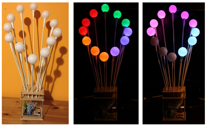
UPDATED: Added two photos of it working
I suppose this is really an Andy Stanford-Clark inspired project that I’ve been working on and off for the last year.
I liked the idea of Cheerlights using the MQTT gateway hosted on the iot.eclipse.org broker at mqtt://iot.eclipse.org/cheerlights.
I also liked the effect of ping pong ball over RGB LED.
So here it is, my wireless cheerlights lamp.
It only needs a 9v power supply to power the ESP8266-12 wireless and the 2 WS2803 chips
Each stalk is a length of 6 core phone cable with 2 cores removed and replaced with a piece of stiff wire. In this case it was wire from a chain link fence with the green plastic coating removed.
The RGB LED was soldered to the remaining four wires and covered in hot melt glue to avoid the wires shorting out. The ping pong ball with a suitable hole was placed on top and the white Sugru moulded around to stick the ball on and hide the hot glue and cable end.
I’d been mocking this all up on a bread board all along, constantly checking that ALL of the LEDs were still working.
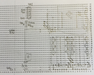
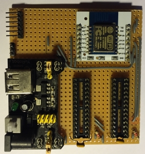
Finally I committed to soldering everything to a board. I carefully planned the layout on paper first as I needed to separate the 3.3v side for the ESP8266 and the 5v side for the LED driver chips. I had been considering powering it from a 5v USB supply and using a 3.3v voltage regulator for the ESP8266 but I couldn’t get it to work reliably. In the end I just soldered the breadboard power supply to the board. This also meant I had an on/off switch, a little power light and fairly sturdy barrel connector for the power.

 Don’t look too carefully, The board is slightly different to the drawing, I switched a couple of ground and 3.3v wires around to make it less cluttered.
The two resistors, one for each chip, are all that are required to limit the current to each LED.
Each LED is controlled by PWM (Pulse Width Modulation) to allow the brightness to be controlled and have a hope of displaying the correct cheerlight colours.
To program the ESP8266 chip in situ I exposed a six pin header to connect a USB to serial programmer. This allows LUA commands and programs to run and be saved to the chip. More about this later.
The other 3 pin jumper allows GPIO0 to be held high (3.3v) for ‘run’ or to be held low (0v) to ‘re-flash’ the ESP8266 should it be necessary to reload the LUA firmware or switch to something else.
Now on to the programming. This is how I get the lamp to connect to my wireless, connect to an MQTT broker, subscribe to the cheerlights topic and finally set the RGB colours.
I use ESPlorer (currently v0.2.0-rc2) on Windows to do the LUA programming.
The first thing to do is get the ESP talking to your Wi-Fi network, this can be done with the following two commands.
wifi.setmode(wifi.STATION)
wifi.sta.config("yourSSID","yourWIFIPASSWORD")
To check this work, the following command should print out the ip address you were given, the netmask and your router ip address.
print(wifi.sta.getip())
The ESP8266 seems to remember this connection and will attempt to connect to this Wi-Fi every time it is switched on.
The next piece of code is a tip that will save your bacon several times at least. The ESP8266 with LUA firmware will at power on run a file called “init.lua” if it exists. This is very useful to run the cheerlights program when the lamp is turned on. But, if you have even a simple error in the program you risk it going into a restart loop requiring a re-flash of the ESP8266. The safest thing to do is make your init.lua a single line similar to the following one.
tmr.alarm(0,5000,0,function() dofile('program.lua') end)
This sets up a timer, 0 in this case, that performs the dofile(‘program.lua’) after the timer expires in 5 seconds. This gives you plenty of time to execute a tmr.stop(0) command to prevent it running your buggy program.
Now the main program which isn’t very big at all. (The version of NodeMCU I run in my ESP8266 was ‘built’ using the nodemcu-build custom build engine where I was able to select the modules I specifically needed to use, mqtt and ws2801, you may now find that they are both included in the normal download)
-- Initialise led interface
ws2801.init(4, 5)
Although I use 2 ws2803 chips they are sufficiently similar to a ws2801 that the module works OK. It needs to be initialised before use and you tell it the two pins it is to talk to, GPIO4 and GPIO5.
-- Set one led on to show starting
ws2801.write(string.char(100, 0, 0))
To provide some feedback during the start up process I turn on LEDs, in this case the first blue one at brightness 100 out of 255.
m=mqtt.Client("uniqueclientid", 120, "", "", 1)
m:on("connect", function(conn) print("connect") end)
m:on("offline", function(conn) print("offline") end)
m:on("message", function(conn, topic, data)
  if data ~= nil then
    print(data)
    if     data == "black"   then ws2801.write(string.char(  0,   0,   0):rep(3))
    elseif data == "blue"    then ws2801.write(string.char(128,   0,   0):rep(3))
    elseif data == "green"   then ws2801.write(string.char(  0, 100,   0):rep(3))
    elseif data == "red"     then ws2801.write(string.char(  0,   0, 128):rep(3))
    elseif data == "cyan"    then ws2801.write(string.char(100, 100,   0):rep(3))
    elseif data == "white"   then ws2801.write(string.char(120, 120, 120):rep(3))
    elseif data == "oldlace" then ws2801.write(string.char( 80,  80, 130):rep(3))
    elseif data == "purple"  then ws2801.write(string.char( 60,   0,  60):rep(3))
    elseif data == "magenta" then ws2801.write(string.char(120,   0, 120):rep(3))
    elseif data == "yellow"  then ws2801.write(string.char(  0, 100, 160):rep(3))
    elseif data == "orange"  then ws2801.write(string.char(  0,  40, 200):rep(3))
    elseif data == "pink"    then ws2801.write(string.char( 40,  30, 180):rep(3))
    else                          ws2801.write(string.char(  0, 100,   0):rep(3))
    end
  end
end)
The code above creates an MQTT Client with an id, keep-alive value of 120 seconds and specifies a clean session each time. Three ‘on’ callback functions are defined for connect, offline and message. The on message is the one that does all of the work, it is called when a message is published to our subscribed topic. It uses a big if elseif ladder to set the first three LEDs (:rep(3) repeats 3 times) to the colour that has been received. The way the ws2803 works means these three values ‘push’ previous values around the loop so the last 4 received colours are always shown. (There seem to be a fair few ‘black’ messages sent though which just turns the 3 LEDs off)
m:connect("iot.eclipse.org", 1883, 0, 0, function(conn)
    print("connected")
    ws2801.write(string.char(0, 100, 0))
    m:subscribe("cheerlights",0, function(conn)
        print("subscribed")
        ws2801.write(string.char(0, 100, 0))
    end)
end)
ws2801.write(string.char(0, 0, 0):rep(12))
This is the bit that connects to the iot.eclipse.org server at port 1883 and when connected, prints “connected” to the serial output, lights the next LED green and then subscribes to the cheerlights topic (and turns another LED green). The last line which sends 0,0,0 12 times turns all the LEDs off but this tends to happen before the connect and subscribe green LEDs turn on.
Future enhancements will probably be a dedicated Raspberry Pi running Node-RED and the mosquito MQTT broker for the lamp to subscribe to. Then it will be able to do more than just the cheerlights, maybe a ‘clock’ display using different colour LED for each hand. A mood lighting mode selecting colours from a colour wheel on an app? I can choose to put the logic either in the lamp in LUA or have the lamp be dumb and display the colours it is told by the Node-RED flow

