Jims blog A list of stuff others might find useful

28/12/2015

The wireless cheerlights lamp

Filed under: esp8266,MQTT — Tags: , , — Jim @ 2:12 pm

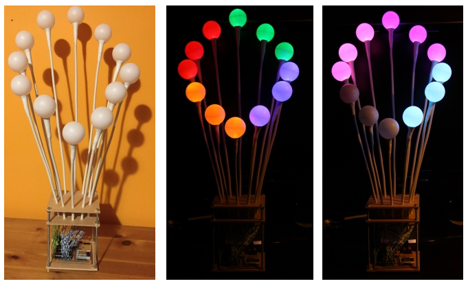
UPDATED: Added two photos of it working

I suppose this is really an Andy Stanford-Clark inspired project that I’ve been working on and off for the last year.

I liked the idea of Cheerlights using the MQTT gateway hosted on the iot.eclipse.org broker at mqtt://iot.eclipse.org/cheerlights.

I also liked the effect of ping pong ball over RGB LED.

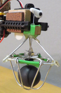
So here it is, my wireless cheerlights lamp.

3views

It only needs a 9v power supply to power the ESP8266-12 wireless and the 2 WS2803 chips

Each stalk is a length of 6 core phone cable with 2 cores removed and replaced with a piece of stiff wire. In this case it was wire from a chain link fence with the green plastic coating removed.

The RGB LED was soldered to the remaining four wires and covered in hot melt glue to avoid the wires shorting out. The ping pong ball with a suitable hole was placed on top and the white Sugru moulded around to stick the ball on and hide the hot glue and cable end.

I’d been mocking this all up on a bread board all along, constantly checking that ALL of the LEDs were still working.

mockup

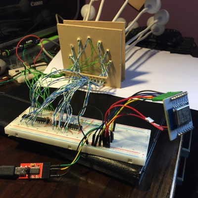
Finally I committed to soldering everything to a board. I carefully planned the layout on paper first as I needed to separate the 3.3v side for the ESP8266 and the 5v side for the LED driver chips. I had been considering powering it from a 5v USB supply and using a 3.3v voltage regulator for the ESP8266 but I couldn’t get it to work reliably. In the end I just soldered the breadboard power supply to the board. This also meant I had an on/off switch, a little power light and fairly sturdy barrel connector for the power.

paperboard
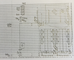
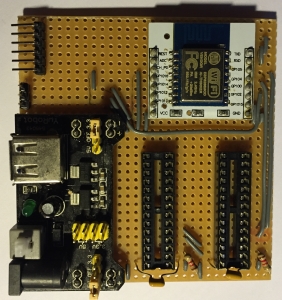
Don’t look too carefully, The board is slightly different to the drawing, I switched a couple of ground and 3.3v wires around to make it less cluttered.

The two resistors, one for each chip, are all that are required to limit the current to each LED.

Each LED is controlled by PWM (Pulse Width Modulation) to allow the brightness to be controlled and have a hope of displaying the correct cheerlight colours.

To program the ESP8266 chip in situ I exposed a six pin header to connect a USB to serial programmer. This allows LUA commands and programs to run and be saved to the chip. More about this later.

The other 3 pin jumper allows GPIO0 to be held high (3.3v) for ‘run’ or to be held low (0v) to ‘re-flash’ the ESP8266 should it be necessary to reload the LUA firmware or switch to something else.


Now on to the programming. This is how I get the lamp to connect to my wireless, connect to an MQTT broker, subscribe to the cheerlights topic and finally set the RGB colours.

I use ESPlorer (currently v0.2.0-rc2) on Windows to do the LUA programming.

The first thing to do is get the ESP talking to your Wi-Fi network, this can be done with the following two commands.

wifi.setmode(wifi.STATION)
wifi.sta.config("yourSSID","yourWIFIPASSWORD")

To check this work, the following command should print out the ip address you were given, the netmask and your router ip address.

print(wifi.sta.getip())

The ESP8266 seems to remember this connection and will attempt to connect to this Wi-Fi every time it is switched on.

The next piece of code is a tip that will save your bacon several times at least. The ESP8266 with LUA firmware will at power on run a file called “init.lua” if it exists. This is very useful to run the cheerlights program when the lamp is turned on. But, if you have even a simple error in the program you risk it going into a restart loop requiring a re-flash of the ESP8266. The safest thing to do is make your init.lua a single line similar to the following one.

tmr.alarm(0,5000,0,function() dofile('program.lua') end)

This sets up a timer, 0 in this case, that performs the dofile(‘program.lua’) after the timer expires in 5 seconds. This gives you plenty of time to execute a tmr.stop(0) command to prevent it running your buggy program.

Now the main program which isn’t very big at all. (The version of NodeMCU I run in my ESP8266 was ‘built’ using the nodemcu-build custom build engine where I was able to select the modules I specifically needed to use, mqtt and ws2801, you may now find that they are both included in the normal download)

-- Initialise led interface
ws2801.init(4, 5)

Although I use 2 ws2803 chips they are sufficiently similar to a ws2801 that the module works OK. It needs to be initialised before use and you tell it the two pins it is to talk to, GPIO4 and GPIO5.

-- Set one led on to show starting
ws2801.write(string.char(100, 0, 0))

To provide some feedback during the start up process I turn on LEDs, in this case the first blue one at brightness 100 out of 255.

m=mqtt.Client("uniqueclientid", 120, "", "", 1)
m:on("connect", function(conn) print("connect") end)
m:on("offline", function(conn) print("offline") end)
m:on("message", function(conn, topic, data)
  if data ~= nil then
    print(data)
    if     data == "black"   then ws2801.write(string.char(  0,   0,   0):rep(3))
    elseif data == "blue"    then ws2801.write(string.char(128,   0,   0):rep(3))
    elseif data == "green"   then ws2801.write(string.char(  0, 100,   0):rep(3))
    elseif data == "red"     then ws2801.write(string.char(  0,   0, 128):rep(3))
    elseif data == "cyan"    then ws2801.write(string.char(100, 100,   0):rep(3))
    elseif data == "white"   then ws2801.write(string.char(120, 120, 120):rep(3))
    elseif data == "oldlace" then ws2801.write(string.char( 80,  80, 130):rep(3))
    elseif data == "purple"  then ws2801.write(string.char( 60,   0,  60):rep(3))
    elseif data == "magenta" then ws2801.write(string.char(120,   0, 120):rep(3))
    elseif data == "yellow"  then ws2801.write(string.char(  0, 100, 160):rep(3))
    elseif data == "orange"  then ws2801.write(string.char(  0,  40, 200):rep(3))
    elseif data == "pink"    then ws2801.write(string.char( 40,  30, 180):rep(3))
    else                          ws2801.write(string.char(  0, 100,   0):rep(3))
    end
  end
end)

The code above creates an MQTT Client with an id, keep-alive value of 120 seconds and specifies a clean session each time. Three ‘on’ callback functions are defined for connect, offline and message. The on message is the one that does all of the work, it is called when a message is published to our subscribed topic. It uses a big if elseif ladder to set the first three LEDs (:rep(3) repeats 3 times) to the colour that has been received. The way the ws2803 works means these three values ‘push’ previous values around the loop so the last 4 received colours are always shown.  (There seem to be a fair few ‘black’ messages sent though which just turns the 3 LEDs off)

m:connect("iot.eclipse.org", 1883, 0, 0, function(conn) 
    print("connected")
    ws2801.write(string.char(0, 100, 0))
    m:subscribe("cheerlights",0, function(conn) 
        print("subscribed")
        ws2801.write(string.char(0, 100, 0))
    end)  
end)
ws2801.write(string.char(0, 0, 0):rep(12))

This is the bit that connects to the iot.eclipse.org server at port 1883 and when connected, prints “connected” to the serial output, lights the next LED green and then subscribes to the cheerlights topic (and turns another LED green). The last line which sends 0,0,0 12 times turns all the LEDs off but this tends to happen before the connect and subscribe green LEDs turn on.

Future enhancements will probably be a dedicated Raspberry Pi running Node-RED and the mosquito MQTT broker for the lamp to subscribe to. Then it will be able to do more than just the cheerlights, maybe a ‘clock’ display using different colour LED for each hand. A mood lighting mode selecting colours from a colour wheel on an app? I can choose to put the logic either in the lamp in LUA or have the lamp be dumb and display the colours it is told by the Node-RED flow


12/01/2014

Node-RED flow for the robot arm

Filed under: iot,Node-RED,robot — Jim @ 4:31 pm

I haven’t really documented the Node-RED flow used for the robot arm anywhere, so this post will try to rectify that.

Node-RED is run on a Raspberry Pi and used as the hub in the process of controlling the robot arm from a client either ‘web’ or Scratch.

processNode-RED starts at boot time and co-ordinates the flow of data to and from the MessageSight broker and the Arduino that is connected to a Pi USB port.

The flow consists of two workspaces, ‘Main flow‘ and ‘Testing and Debug’. Clicking the Main flow link will open a Node-RED export json file of all nodes on that workspace (The testing workspace just contains some inject and debug nodes used during development)

The main part of the flow is shown below, each of the nodes will be explained.

Node-RED-flow

3 comment blocks in the flow allow for some basic documentation within Node-RED itself.

Starting from top left. The MQTT node ‘Retrieve commands’ subscribes to the <stem>/input topic on the MessageSight broker. (In this case stem is a part of the topic tree relevant to this application)

Output from the MQTT node is passed directly to a ‘serial out’ node that is connected to /dev/tty/ACM0. This is the where the Arduino serial interface appears. The Arduino takes the command and actions it as described in the previous post.

Next we have a ‘serial in’ node also connected to /dev/tty/ACM0, this receives all of the responses back from the Arduino. The flow splits here.

The ‘Discard 2’ function node contains the following code and the comments explain its reason for existing.

// The first two records from the serial node are not valid data
// but initialisation lines from the motor/servo driver
// Don't publish them as valid positions else we wipe out the last
// good retained position
// Use one of them to trigger the pausing of the motion detection
// in motion

// Initialise count if it doesn't have a value already
context.count = context.count || 0;
// Increase count for every msg flowing through
context.count += 1;

// If the count has gone over 2
if (context.count > 2) {
   // we have valid records now, so return to first output
   return [ msg, null ];
} else if (context.count == 1) {
   // This is the second record through, send this to the second output
   // we'll use this one to trigger a pause of the motion detection
   return [ null, msg ];
} else {
   // The very first record gets swallowed
   return [ null, null ];
}

For output one another function node just sets the msg.retain=true so that the last position reported will always be available to clients, then it is on to an ‘mqtt out’ node to publish the position status to the <stem>/output topic.

As explained in the code the one message that is sent to output 2 flows into an ‘http request’ node. The URL http://localhost:8080/0/detection/pause ‘pauses’ the motion detection function of the motion program that was started at boot time. Motion detection is always active from boot and must be paused if it is not required. In this application, only snapshots are used.

It is the other output out of the ‘serial in’ node that is used to ‘trigger motion snapshot’. It is another ‘http request’ node with a URL of  http://localhost:8080/0/action/snapshot this tells motion to write the last image it took to disk as a jpg file. Motion has been configured to take images at 15 frames a second so the last image could be up to 66ms old and we could miss the event we were trying to capture. This is why there is a ‘delay so we don’t miss the action’ delay node set at 0.1 seconds to wait and ensure the event has occurred before we take the snapshot.

At this point we’ve only caused a snapshot jpg to be written to ‘disk’ (SD card in this case on a Raspberry Pi) So the last part of the flow has to retrieve and publish it.

‘watch for snapshot’ is a ‘watch’ node that uses fs.notify under the covers to keep an eye on a certain directory, where the snapshots are written, and report a change in the directory. There was an initial problem here, as motion wrote the jpg file to a directory, more than one change was seen and sent through the flow for each file. This was overcome by using a small ‘on_picture_save’ shell script within the motion configuration file. Each time a jpg is saved this script is called with the file name as a parameter.

#!/bin/bash
fname=`basename $1`
sudo ln -s $1 /home/pi/images/new/$fname
sleep 10
sudo rm $1
sudo rm /home/pi/images/new/$fname

This script symlinks the image into another directory waits 10 seconds and then deletes the original and the symlink. We assume that the file has been read and published before the 10 seconds is up. This means we keep the disk clean and don’t accumulate lots of images or symlinks. (Each snapshot image has a date, time and frame stamped name).

‘convert image’ is an exec node which calls a python script when it is told a change has occurred in the symlink directory.

#!/usr/bin/python
import base64
import commands
import sys
filename = '/home/pi/images/new/'+sys.argv[1]
try:
with open(filename):
imagestring = commands.getoutput('cat '+filename)
print bytes(base64.b64encode(imagestring))
except IOError:
print >> sys.stderr, 'symlink delete'

The watch node also reports on file deletes as well as creates so this script checks if the file exists when it is called. If the file doesn’t exist any more then it must have been a delete. If it can be read it is, into an string and then encoded into base64 before being printed onto stdout.

One more function node is needed to add the retain flag to this encoded image but also annoyingly ignore empty messages that flow through stdout even if the file didn’t exist

// Need to set retain flag on the image message only if
// it is an image and not a null
if (msg.payload.length == 0) {
   return null;
} else {
   msg.retain=true;
   return msg;
}

Finally the image is published to the <stem>/image topic through an mqtt node.

06/01/2014

Arduino code for the robot arm

Filed under: arduino,iot,robot — Jim @ 1:32 pm

Following on from the previous post, I thought I should explain the Arduino code used to control the robot arm

You can download the code from here

In summary the program sits in a loop waiting for commands from the serial port, it responds to them by moving the arm in the requested direction and then reports the current positional state of each of the joints. Asynchronously it will adjust the wrist joint to maintain the ‘hand’ as horizontal as it can within a few degrees.

Here then is my explanation for the parts of the code. I’ve left out the comments that are in the code where they would just be duplicated.

First we include the headers needed for the motor shield and to control the servo.

#include <Wire.h>
#include <Adafruit_MotorShield.h>
#include <Servo.h>

Then we create the motor shield, motor and servo objects

Adafruit_MotorShield AFMS = Adafruit_MotorShield();
Adafruit_DCMotor *myShoulder = AFMS.getMotor(1);
Adafruit_DCMotor *myElbow    = AFMS.getMotor(2);
Adafruit_DCMotor *myWrist    = AFMS.getMotor(3);
Adafruit_DCMotor *myBase     = AFMS.getMotor(4);
Servo servo;

These servo position values of 100 and 135 are the absolute positions of the servo arm needed to open and close the clamp

#define OPEN 100
#define CLOSE 135

On the Arduino UNO you can only attach interrupts to pins 2 and 3

#define FRONTPIN 2
#define BACKPIN 3

Although not exposed in the scratch or web applications, the motor run time can be changed to one of 6 values. (array position 0 is not used only 1 to 6) The default duration used is 100ms in position 4

int motor[] = { 0, 15, 30, 60, 100, 250, 500 };
int duration = 4;
int motorTime = motor[duration];

The default clamp state is open at startup corresponding to servo value 100

int clampState = OPEN;

Here we set some variables that are needed in the interrupt routines so they are declared volitile, the de-bounce time means we don’t get too many false triggers of the code.

unsigned long debounce = 50;
volatile int frontPinState = 0;
volatile int backPinState = 0;
volatile unsigned long frontLastTime = 0;
volatile unsigned long backLastTime = 0;

All of the initialisation is done in the setup() function.

  • Set the interrupt pins to input and set their pull-up to high
  • Start the serial port at 19,200 baud
  • Initialise the motor shield
  • Set the initial ‘speed’ of the motors, which won’t change. 0 is off, 255 is max speed. These are 3v motors on a 5v supply so not driving at full speed
  • Attach the servo to pin 9, this is exposed on the motor shield as a 3 pin header and makes it simple to plug a servo in. Then ‘write’ the value 100 to open the clamp if not already.
  • Attach the sub-routines ‘front’ and ‘back’ to interrupt 0 and 1 respectively and specify they are to trigger on a pin CHANGE
  • delay for 1/4 second and report the first set of position values.
void setup() {
   pinMode(FRONTPIN, INPUT);
   pinMode(BACKPIN, INPUT);
   digitalWrite(FRONTPIN, HIGH);
   digitalWrite(BACKPIN, HIGH)
   Serial.begin(19200);
   AFMS.begin();
   myShoulder->setSpeed(170);
   myElbow->setSpeed(170);
   myWrist->setSpeed(170);
   myBase->setSpeed(180);
   servo.attach(9);
   servo.write(clampState);
   attachInterrupt(0, front, CHANGE);
   attachInterrupt(1, back, CHANGE);
   delay(250);
   readsensors();
}

The main loop, first set some variables

void loop() {
   String validCommands = "rsSeEwWbBcd";  // The valid commands we will accept for control
   bool cmdComplete = false;
   static int parm = 0;
   static char command;                   // Command character

Now if a character arrives on the serial input build up a command until a comma terminates it

   while ((Serial.available() > 0) & (!cmdComplete)) {
      char ch = Serial.read();
      if (ch != ',') {                 // Not a comma
         if (ch >= '0' && ch <= '9') {  // Accumulate the decimal parameter into parm if character read is numeric
            parm = parm * 10 + ch - '0';
         } else if (validCommands.indexOf(ch) != -1) {
            command = ch;                // If it's not numeric see if it is one of our valid commands
         } else {
            Serial.println("Invalid command");
         }
      } else {
         cmdComplete = true;            // When we get a comma the command is complete
      }
   }

If cmdComplete is true then we can action that. Use a big switch statement to decide what to do for each command

   if (cmdComplete) {
      cmdComplete = false;
      // Do the action depending on the character received.
      switch (command) {
         case 'r':                   // r just read the sensors and write their values to serial output, don't move
            break;
         case 's':                   // s moves the shoulder forwards
            moveShoulder(FORWARD);
            break;
         case 'S':                   // S moves the shoulder backwards
            moveShoulder(BACKWARD);
            break;
         case 'e':                   // e moves the elbow down
            moveElbow(FORWARD);
            break;
         case 'E':                   // E moves the elbow up
            moveElbow(BACKWARD);
            break;
         case 'w':                   // w moves the wrist down
            moveWrist(FORWARD);
            break;
         case 'W':                   // W moves the wrist up
            moveWrist(BACKWARD);
            break;
         case 'b':                   // b turns the base clockwise (looking down)
            moveBase(FORWARD);
            break;
         case 'B':                   // B turns the base anti-clockwise (looking down)
            moveBase(BACKWARD);
            break;
         case 'c':                   // c toggles the clamp open and closed
            clamp();
            break;
         case 'd':                   // Set the duration of motor run time
            duration = parm;
            motorTime = motor[duration];
            break;
         default:
            break;
      }

After the command has been actioned call readsensors() to report all the joint positions out to the serial port, default the command to an ‘r’ and the parameter to 0

      readsensors();
      command = 'r';
      parm = 0;
   }

Before ending the loop and checking for more characters, check to see if either of the interrupt routines have been triggered by the tilt switch. If either has, move the wrist in the opposite direction to keep it level, reset the state and report all the new joint positions.

   if (frontPinState == 1) {
      moveWrist(BACKWARD);
      frontPinState = 0;
      readsensors()
   }
   if (backPinState == 1) {
      moveWrist(FORWARD);
      backPinState = 0;
      readsensors();
   }
}

Now the subroutines. First the readsensors() routine which will read the analog values of all four potentiometers into variables and then concatenate the values together to print to the serial output.

void readsensors() {
   delay (5);                            // Delay between analog reads is meant to allow time for 'settling'
   int sensorValue1 = analogRead(A0);    // Position of shoulder
   delay (5);
   int sensorValue2 = analogRead(A1);    // Position of elbow
   delay (5);
   int sensorValue3 = analogRead(A2);    // Position of wrist
   delay (5);
   int sensorValue4 = analogRead(A3);    // Position of base

   // State of all sensors is reported in one comma separated line
   Serial.println(String(sensorValue4) + ","
                + String(sensorValue1) + ","
                + String(sensorValue2) + ","
                + String(sensorValue3) + ","
                + ((clampState == OPEN) ? "open" : "closed") + ","
                + String(duration));
}

The next four routines ‘run’ the motors for the corresponding joint in the required direction for the pre-defined run time before stopping the motor again.

void moveShoulder(int dir){
   myShoulder->run(dir);
   delay(motorTime);
   myShoulder->run(RELEASE);
}

void moveElbow(int dir){
   myElbow->run(dir);
   delay(motorTime);
   myElbow->run(RELEASE);
}

void moveWrist(int dir){
   myWrist->run(dir);
   delay(motorTime);
   myWrist->run(RELEASE);
}

void moveBase(int dir){
   myBase->run(dir);
   delay(motorTime);
   myBase->run(RELEASE);
}

The clamp() routine toggles the clamp, if it is open it will close it and vice versa. The servo is moved in increments of 5 between the open (100) and closed (135) values with a small delay to slow the movement down.

void clamp() {
   int pos = 0;
   if (clampState == OPEN) {                     // If the clamp is currently open
      for(pos = OPEN; pos <= CLOSE; pos += 5) {
         servo.write(pos);
         delay(50);
      }
      clampState = CLOSE;                        // now it's closed
   } else {                                      // else step back the other way
      for(pos = CLOSE; pos>= OPEN; pos -= 5) {
         servo.write(pos);
         delay(50);
      }
      clampState = OPEN;
   }
}

The last two routines are the ones attached to the the interrupt pins 2 and 3. The routines are called when the respective pin changes from low to high or high to low. We’ll only trigger a wrist movement if debounce milliseconds have passed between successive calls. (I’m not sure this is really a true ‘debounce’ like you would a switch but it seems to work OK). All the routine does is to set the *PinState flag to 1, it is checked in the main program loop.

void front() {               // The interrupt routine, called when front pin changes
   if((long)(millis() - frontLastTime) >= debounce) {  
      frontLastTime = millis();
      frontPinState = 1;
   }
}

void back() {               // As above except for the back pin
   if((long)(millis() - backLastTime) >= debounce) {
      backLastTime = millis();
      backPinState = 1;
   }
}

05/01/2014

The ‘Thing’

Filed under: iot,robot — Jim @ 2:43 pm

What is the ‘Thing’?

A couple of colleagues and I have entered an ‘Internet of things’ challenge at work.

The challenge is to control a robot or ‘thing’ using some mandatory technologies. They are MQTT, node-RED and an IBM MessageSight, either the real thing or MessageSight for developers.

For our entry the ‘thing’ is going to be a modified OWI Robot arm available from maplin. The arm comes as a kit and has to be assembled but the instructions were very easy to follow. This kit was supplied with a USB PC interface. This allows the robot to be controlled from a PC using the supplied software.

robotic-arm-kit-with-usb-pc-interface

The fully assembled kit

OWI-arm-sw

The supplied software GUI


As supplied there is no feedback at all from the arm, the joints move in the requested direction for as long as the mouse button or a key is pressed.

To be able to remotely control the arm then the positions of each the joints needs to be returned. I had seen other attempts to instrument the arm. This one is the closest to how I have modified the arm. It has a limitation though that it restricts the movement of the base which I wanted to avoid as my plans required the base to have at least 200 degrees of freedom. This required some imaginative thought on how to measure the rotational position but more on that later.

Reading the 4 potentiometer sensor values was going to need analogue to digital converters, this meant an arduino was probably going to be the easiest way to control the whole arm.

The 3v DC motors in the joints were powered and controlled by 4 D cell batteries in the base and a small circuit board just above them. Although I found it was possibly to control the motors through the USB interface from a Raspberry Pi using c from here, I decided to control the motors with the arduino too. As I had four motors to control I have used an Adafruit Motor/Stepper/Servo Shield for Arduino v2 Kit – v2.0 which I got from Phenoptix in the UK.

Now for some detail, the sensors, 3 of them are little square 10k pots and one is a 10k 15 turn side slot pot. The first two for the shoulder and elbow joints were fairly easy to mount.

Shoulder-sensor

The shoulder sensor

The shoulder sensor is hot glued on the axis of the joint and a sewing needle used as a link to a fixed point on the base.


elbow-sensor

The elbow sensor

The elbow sensor is the same as the shoulder, hot glued on the axis of the joint but the needle is attached to the rotating part of the elbow this time.


wrist-sensor

The wrist sensor

The wrist sensor is a bit different, if it had been stuck on the axis like the other two then the movement would have been restricted. Instead two points on the arms that move relative to each other were used.

This does mean that the free end of the needle needs to move in and out of the pivot point and rotate. It also means the output of the pot will be non-linear but this doesn’t matter too much for another reason.


base-sensor

The base sensor

The base sensor was the most awkward. As mentioned before if a pot was used on the axis of the base, the logical fixed point would be on top of the battery box, This would restrict the movement of the base to about 45 degrees either side of the centre line. After considering many option including rubber wheels pressing against a roughened base, gear wheels turned by a toothed belt around the base, I went with the current solution. I measured the part of the circumference of the base could actually travel and knowing that I could use a maximum of 15 turns of the cermet pot a wheel of around 1cm diameter would be enough to provide a good range of readings and give an acceptable resolution.

The extending badge holder had the ideal cord for the little wheel to guide around the base as it turned clockwise and enough spring power to keep tension around the main wheel when it returned. (The little piece of wire on the right hand side was to overcome a problem where the cord would cross and slip on the the wheel)

Now for the grip. I had always intended for the robot arm to pick up and drop a ball. Something the size of a mouse ball. The grip that the arm comes with though, although capable of picking up the ball had no feedback to tell if the ball was being gripped or not. (I did think later that I could have used two ‘cups’ in the jaws, allowing the grip to close to a known position and pick up the ball)

I went with another solution, the grab.

the-grab

The grab

The grab is made from stiff wire. There are three fingers that pivot on the triangular frame and are moved from the open to closed by pin that moves up and down controlled by a small servo motor. The whole grab assembly is held fairly lightly in the jaws and a couple of wooden blocks stop the assembly twisting. (Luckily the motor driver shield also exposes the 2 servo motor ports, one of which is used here)


This brought me to the next issue. The grab should stay as vertical as possible to be effective but moving the shoulder or elbow on their own causes the grab to move away from vertical requiring movement of the wrist to bring it back. I did contemplate autonomously moving the wrist by mathematically working out the angles from the positions of shoulder and elbow sensors. My final solution was the ’tilt switch’. This sits on top of the wrist and asynchronously adjusts the wrist position to keep it level and the grab vertical.

The arduino UNO that we are using has two pins that can have interrupt routines added to them. int.0 and int.1 are available on digital pins 2 and 3 respectively. When you attach your routines to each of the pins you specify which ‘mode’ should trigger the routine. The options for an UNO are LOW which triggers when the pin is low, CHANGE triggers when ever the pin changes value, RISING triggers when going from low to high and FALLING triggers when going from high to low.

Using CHANGE for both pins gave the best results with a bit of debounce code. Now for the actual switch, I did consider ‘mercury’ tilt switches or components like them and I may have got them to work but the resolution didn’t seem to be good enough. I also considered a solid state solution using an accelerometer breakout board but that seemed a bit over the top. So I implemented a rolling ball solution.

tilt-switch

Tilt switch

The ball bearing rolls along the lower two pieces of wire that are bent slightly to control the sensitivity of the switch. The rails are all electrically grounded by the blue wire. When the ball touches either the front or back pin it causes a change to pins 2 or 3 which triggers the interrupt routine to signal that the wrist is tipped too far forward or back and that a corresponding move should be made to correct that.


The arm is controlled by sending ‘commands’ to the Arduino serial port. It has a fairly simple command structure that consists of a single case sensitive character followed by an option numeric parameter and ended by a comma.

  • b turns the base anti-clockwise looking above, B turns it clockwise
  • s moves the shoulder forwards and S backwards
  • e moves the elbow down and E up
  • w tilts the wrist down and W tilts it up
  • c toggles the clamp/grip between being open or closed
  • (d<1-6> set the motor run duration to predefined lengths of time but in this application we stay fixed at 4)
  • (r reports the position of all the sensors without making any moves, also not used)

The position of all of the sensors is reported out of the serial port after any movement of the arm or grip including after an adjustment of the wrist triggered by the tilt switch. This is always in the form <base value>, <shoulder value>,<elbow value>,<wrist value>,<open|closed for grip status>,<motor run duration>

whole arm

The whole arm

18/09/2011

Recording light levels to a Currentcost display

Filed under: currentcost,devboard,solarcell — Jim @ 5:08 pm

This is my first useful (I hope) blog post detailing what I’ve been trying to get working for the past week.

I wanted to be able to record and graph the light levels out of my window in a similar way to how I do power and temperature with my Currentcost display.

I bought a Current cost analogue development board from Ebay  and found a bit more about the specification from the Current Cost Technical Blog.

It seems that the “4P4C jack” that is referred to in the text of the spec has been replaced by the 3 blue wires. It caused me some confusion working out that it is not necessarily the left most blue wire, as shown in the photo, that is the input. In my case the blob of glue meant the middle wire was the positive input.

The Solar cell I hacked out of a garden light. It produces from 0V to 3.2V within the spec of the board which will accept 0-4V.

I couldn’t get the board to transmit a value using just the solar cell, although 1 or 2 AA batteries across the input would display a number of watts. So I tried a little transistor circuit shown below.Schematic of the circuit

The finished light sender looks like this

The finished sensor

The CC display shows anywhere from low 10s of watts when the solar panel is covered up to a maximum of 23.1KW when exposed to light. The 23.1KW value is shown for any light level above dull daylight so I may have to give the solar cell some dark glasses or cover bits of it with masking tape to get it to peak for bright sunlight.

I hope that is useful to someone. I’ve now got to integrate it into my rrd database and graphing scripts, maybe I’ll post again with some of the output in a few weeks.

10/09/2011

Let us see if I can write a useful, informative blog

Filed under: first — Jim @ 7:03 pm

I’ve always meant to start writing a blog but have never seemed to get round to it.

I’ve often thought that all the googling and hacking I’ve done to get some piece of software or hardware working should be written down somewhere, so it may help others in the same way my goggle hits did.

Jim….

Powered by WordPress