What is the ‘Thing’?
A couple of colleagues and I have entered an ‘Internet of things’ challenge at work.
The challenge is to control a robot or ‘thing’ using some mandatory technologies. They are MQTT, node-RED and an IBM MessageSight, either the real thing or MessageSight for developers.
For our entry the ‘thing’ is going to be a modified OWI Robot arm available from maplin. The arm comes as a kit and has to be assembled but the instructions were very easy to follow. This kit was supplied with a USB PC interface. This allows the robot to be controlled from a PC using the supplied software.
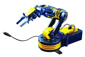
The fully assembled kit
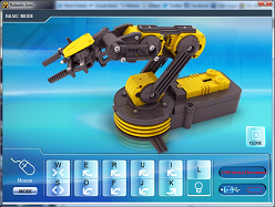
The supplied software GUI
As supplied there is no feedback at all from the arm, the joints move in the requested direction for as long as the mouse button or a key is pressed.
To be able to remotely control the arm then the positions of each the joints needs to be returned. I had seen other attempts to instrument the arm. This one is the closest to how I have modified the arm. It has a limitation though that it restricts the movement of the base which I wanted to avoid as my plans required the base to have at least 200 degrees of freedom. This required some imaginative thought on how to measure the rotational position but more on that later.
Reading the 4 potentiometer sensor values was going to need analogue to digital converters, this meant an arduino was probably going to be the easiest way to control the whole arm.
The 3v DC motors in the joints were powered and controlled by 4 D cell batteries in the base and a small circuit board just above them. Although I found it was possibly to control the motors through the USB interface from a Raspberry Pi using c from here, I decided to control the motors with the arduino too. As I had four motors to control I have used an Adafruit Motor/Stepper/Servo Shield for Arduino v2 Kit – v2.0 which I got from Phenoptix in the UK.
Now for some detail, the sensors, 3 of them are little square 10k pots and one is a 10k 15 turn side slot pot. The first two for the shoulder and elbow joints were fairly easy to mount.
The shoulder sensor
The shoulder sensor is hot glued on the axis of the joint and a sewing needle used as a link to a fixed point on the base.
The elbow sensor
The elbow sensor is the same as the shoulder, hot glued on the axis of the joint but the needle is attached to the rotating part of the elbow this time.
The wrist sensor
The wrist sensor is a bit different, if it had been stuck on the axis like the other two then the movement would have been restricted. Instead two points on the arms that move relative to each other were used.
This does mean that the free end of the needle needs to move in and out of the pivot point and rotate. It also means the output of the pot will be non-linear but this doesn’t matter too much for another reason.
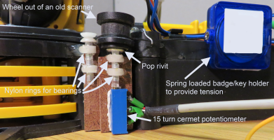
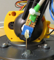
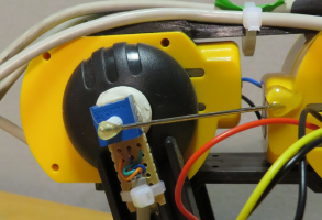
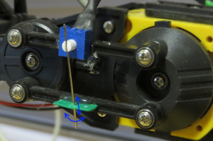
The base sensor
The base sensor was the most awkward. As mentioned before if a pot was used on the axis of the base, the logical fixed point would be on top of the battery box, This would restrict the movement of the base to about 45 degrees either side of the centre line. After considering many option including rubber wheels pressing against a roughened base, gear wheels turned by a toothed belt around the base, I went with the current solution. I measured the part of the circumference of the base could actually travel and knowing that I could use a maximum of 15 turns of the cermet pot a wheel of around 1cm diameter would be enough to provide a good range of readings and give an acceptable resolution.
The extending badge holder had the ideal cord for the little wheel to guide around the base as it turned clockwise and enough spring power to keep tension around the main wheel when it returned. (The little piece of wire on the right hand side was to overcome a problem where the cord would cross and slip on the the wheel)
Now for the grip. I had always intended for the robot arm to pick up and drop a ball. Something the size of a mouse ball. The grip that the arm comes with though, although capable of picking up the ball had no feedback to tell if the ball was being gripped or not. (I did think later that I could have used two ‘cups’ in the jaws, allowing the grip to close to a known position and pick up the ball)
I went with another solution, the grab.
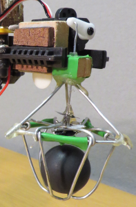
The grab
The grab is made from stiff wire. There are three fingers that pivot on the triangular frame and are moved from the open to closed by pin that moves up and down controlled by a small servo motor. The whole grab assembly is held fairly lightly in the jaws and a couple of wooden blocks stop the assembly twisting. (Luckily the motor driver shield also exposes the 2 servo motor ports, one of which is used here)
This brought me to the next issue. The grab should stay as vertical as possible to be effective but moving the shoulder or elbow on their own causes the grab to move away from vertical requiring movement of the wrist to bring it back. I did contemplate autonomously moving the wrist by mathematically working out the angles from the positions of shoulder and elbow sensors. My final solution was the ’tilt switch’. This sits on top of the wrist and asynchronously adjusts the wrist position to keep it level and the grab vertical.
The arduino UNO that we are using has two pins that can have interrupt routines added to them. int.0 and int.1 are available on digital pins 2 and 3 respectively. When you attach your routines to each of the pins you specify which ‘mode’ should trigger the routine. The options for an UNO are LOW which triggers when the pin is low, CHANGE triggers when ever the pin changes value, RISING triggers when going from low to high and FALLING triggers when going from high to low.
Using CHANGE for both pins gave the best results with a bit of debounce code. Now for the actual switch, I did consider ‘mercury’ tilt switches or components like them and I may have got them to work but the resolution didn’t seem to be good enough. I also considered a solid state solution using an accelerometer breakout board but that seemed a bit over the top. So I implemented a rolling ball solution.

Tilt switch
The ball bearing rolls along the lower two pieces of wire that are bent slightly to control the sensitivity of the switch. The rails are all electrically grounded by the blue wire. When the ball touches either the front or back pin it causes a change to pins 2 or 3 which triggers the interrupt routine to signal that the wrist is tipped too far forward or back and that a corresponding move should be made to correct that.
The arm is controlled by sending ‘commands’ to the Arduino serial port. It has a fairly simple command structure that consists of a single case sensitive character followed by an option numeric parameter and ended by a comma.
- b turns the base anti-clockwise looking above, B turns it clockwise
- s moves the shoulder forwards and S backwards
- e moves the elbow down and E up
- w tilts the wrist down and W tilts it up
- c toggles the clamp/grip between being open or closed
- (d<1-6> set the motor run duration to predefined lengths of time but in this application we stay fixed at 4)
- (r reports the position of all the sensors without making any moves, also not used)
The position of all of the sensors is reported out of the serial port after any movement of the arm or grip including after an adjustment of the wrist triggered by the tilt switch. This is always in the form <base value>, <shoulder value>,<elbow value>,<wrist value>,<open|closed for grip status>,<motor run duration>

The whole arm
[…] on from the previous post, I thought I should explain the Arduino code used to control the robot […]
Pingback by Arduino code for the robot arm « Jims blog — 06/01/2014 @ 1:33 pm